Yeah, so? First riding bicycles, now what?
Well, I’ve gone back to my electronics roots and have recreated a crystal radio that was my first electronics project back in about fifth or sixth grade.
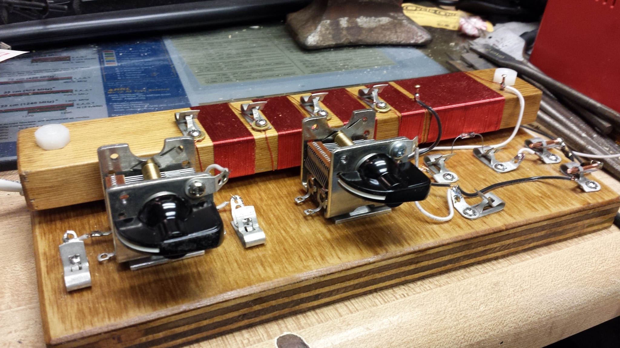
Finished set. Click to enlarge.
Back in my early teen years, I was a fierce reader. I spent many hours in the Children’s and Young Adult sections of the Lockport Library. I made at least one trip a week during summer vacation bringing back an armfull of books each time.
I read all sorts of things, including science fiction, but that’s another story. The library had a small section of books on technology aimed at young people. In it I discovered a series of books by Alfred Powell Morgan and made my way through some of them.
These books were instrumental in my interest in electronics at an early age. If I had not read them as a pre-teen, I wonder what path my life would have followed? If they didn’t exist, or my library didn’t have them, what eventual career path would I have followed? Would there have been some other path into an interest in electronics, or would I have been an insurance salesman or lawyer?
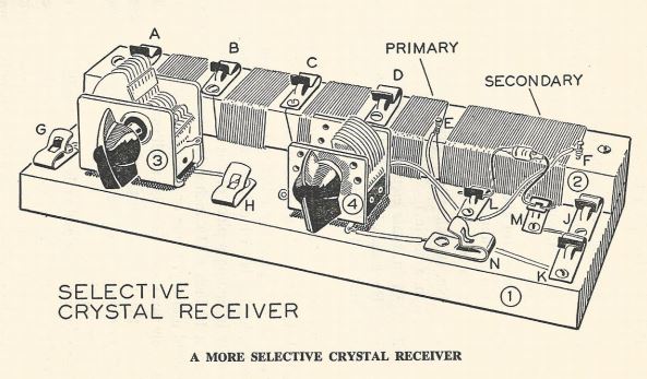
This was the picture in the book that caught my imagination
There were a number of them and I’m sure the Lockport Library didn’t have all of Morgan’s books, but the ones on electricity and electronics were there and I read through them all. Several times. In one of them, The Boys Second Book of Radio and Electronics, I found the crystal set. Not just any crystal set. I’d seen the typical oatmeal box sets and the foxhole radios, that you’d find in the Boy Scout Handbook. This was more than that. It was both better than the average simple set, and it was practical. It contained no exotic parts. Nothing difficult to make at home. Both performance and basic at the same time. I had to build this crystal set.
I don’t recall how it was arranged, or how much pleading I had to do, but eventually, my father took me to Buffalo one Saturday morning to shop for the parts needed. Back then, there were several electronics parts outlets on Main Street Buffalo. We hit a couple to get what I needed.
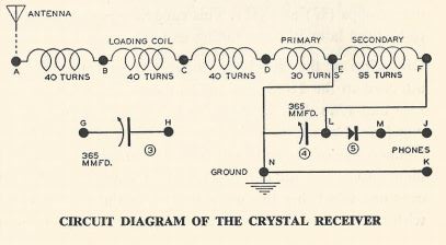
The schematic diagram
The radio got constructed reasonably fast and reasonably close to the description in the book. I don’t remember much about the actual building of it, but it took some soldering and some woodworking and some improvisation. Although I followed the book closely, there were some differences. I don’t think I ever sealed the wood with shellac as specified. It didn’t seem to hurt and I didn’t expect to get the radio wet, so I didn’t worry about it. I didn’t use “Escutcheon Pins” for the two coil terminations. I had no idea where to get such things, and small brads seemed to work just fine. Most of it was pretty close to the book, though.
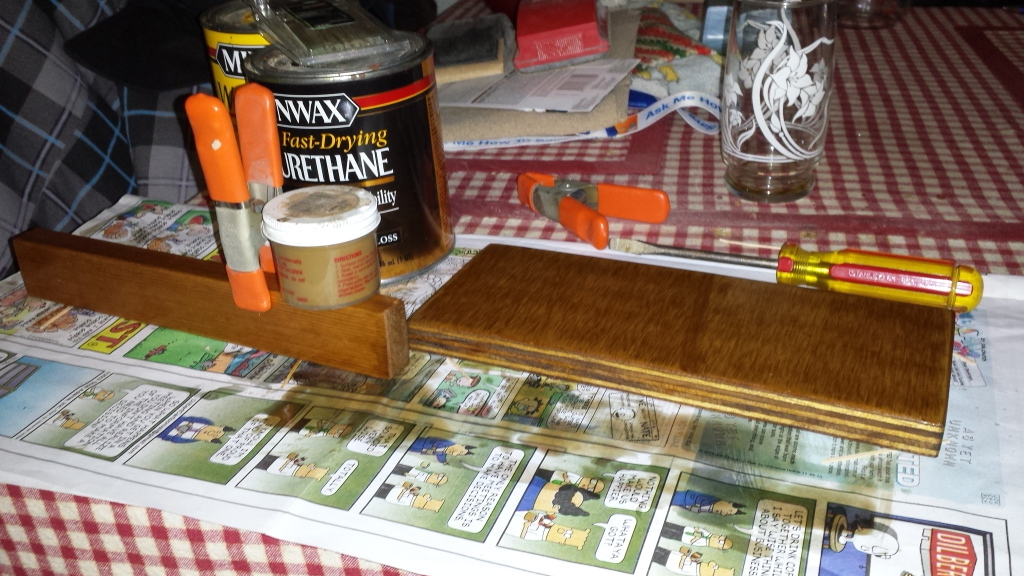
Preparing the wood parts
Recently, I had a conversation with an old friend, who also had enjoyed the Morgan books back in the day. They were a common bond that started off a lifelong friendship. He mentioned that he had a copy of the book and offered to let me borrow it. I responded that I’d like to copy the article on the crystal set I had built and he scanned it and emailed it to me. I had accumulated some of the parts for a crystal set and had been hanging on to them for some years. This was the push I needed to get going and recreate my boyhood set.
I had been given a set of high-impedance headphones a while back. A co-worker had mentioned that he has some electronics ‘stuff’ and asked if I wanted any of it. He brought it to work and gave it to me, saying I could have any of it I wanted, just throw the rest out. There were some cables and not very special stuff, but a set of vintage headphones in perfectly useable condition were in there. Jackpot!
You can’t get those headphones anymore. They just aren’t made. They are even scarce on eBay. I don’t know what ever happened to the pair I got on my trip to Buffalo. They were still common then. I had one other set long ago, a better quality set that I had repaired to get working, but they are long gone now as well. The crystal set aficionados make their own using earpieces out of surplus sound-powered phones, but those are even scarce and can only be found occasionally online. So I had the one critical piece of “unobtanium” I needed, might as well go on with it.
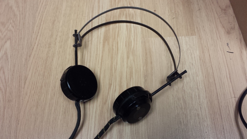
Old high-impedance headphones
So, I went online and started looking for the parts I would need to build the set. The variable capacitors are getting scarce too, but can still be salvaged from old radios. But there is one source for new ones – the Crystal Set Society. Yes, there is a group dedicated to the preservation of the science of crystal sets and related articles. And they sell parts. Everything but the headphones. They still offer the less-sensitive crystal/piezo earplugs you’ve seen in the cheap science fair radio kits, and they do work, but not quite like the real headphones. But many of the other parts needed are for sale on their site, including brand new variable capacitors that they had made especially for them. I made a list of things I might need and my finger must have slipped on the ‘Submit’ button, because before I knew it, they were at my door!
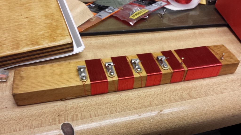
The inductor coil windings
Another scarce part they had was Fahnestock Clips. They are a vintage wire connection with a springy piece formed in a way that you can insert a wire and let go and it will grip the wire and make a connection. Very old-fashioned and nearly impossible to find anymore. You might find them in Mouser or Allied’s catalog, but the time it would take to find them buried in the fine print isn’t worth it.
So they were kind of one-stop crystal radio shopping. I ordered magnet wire, two capacitors, Fahnestock clips, solder lugs, some mounting shims they recommended for the capacitors and some 1N34 diodes for good measure. The diodes I have on hand, but figured I’d get some more.

Parts being added to the base breadboard style
I wanted to do a better job on the construction end of things this time, after all, I am older and more experienced, I ought to be able… I selected some wood to use and cut a piece of plywood for the base and a piece of 3/4 x 1 1/2 inch pine for the coil form. This radio is odd in that it uses a rectangular coil form, something not usually done, but for accuracy’s sake, I stuck to it. I had some polyurethane left over from another project, as well as some Honey Walnut stain, so I sanded the boards smooth and finished them. Boy, it takes forever for that stuff to dry when you’re in a hurry. I left them in the oven overnight to let the pilot light keep them warm and dry faster. By morning, they were ready to work on.
First, I wound the coils. When I went to the hardware store to get wood screws to hold down the clips, I looked up and what was staring at me? Escutcheon Pins! So, I made it authentic and used them. The wire was soldered to the first pin and I was off winding the first section of 95 turns. It sounds like a lot, but it actually went quickly. Keeping the wire taught as you turn the form and keeping count of the number of turns is the hard part. The wire had to be sanded clean of it’s enamel coating before making the connection at the pins, but a little effort made sure that a good solder connection was the result. The rest of the sections were smaller and went quickly, but instead had a Fahnestock clip and screw at each section. I only overtightened one once, which broke the wire under the screw. I think that section might be one turn short now, but maybe I miscounted too.
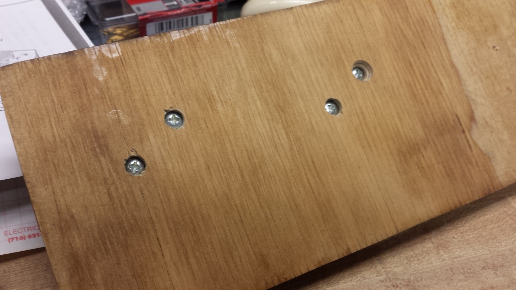
To mount the capacitors I counter sank the screws to get the right length and so the bottom was flat.
Next, I began to work on the base. Mounting the capacitors was somewhat tricky. They mount using threaded 6-32 holes in the bottom. There are four, but I only used two, diagonally. I had 3/4 long screws, which worked out perfectly. The wood was 3/4 inch thick and I wanted the heads recessed to keep the bottom flat. Also, the screw threads can only go into the capacitor a little way or else they will contact the stationary plates and short it out. The countersinking allowed me to control exactly how much thread entered the capacitor.
Fahnestock clips were mounted as suggested by the book. I measured almost nothing, just eyeing things for placement. Most of it is not critical. Wire connections were made where needed, both from clip to clip and to the capacitors. I used a small wood screw and a small washer for each coil tap, but on the base, I used a solder lug instead of the washer. Some old style Fahnestock clips had a solder tab on them. Others didn’t. you can always make a connection by wrapping a wire under the screw, but I thought the lugs were better for the permanent connections. Solder lugs were also used to connect to the frame (rotor) of the capacitors. I didn’t have screws short enough for that, but used what I had and cut off the excess flush with a Dremel tool.
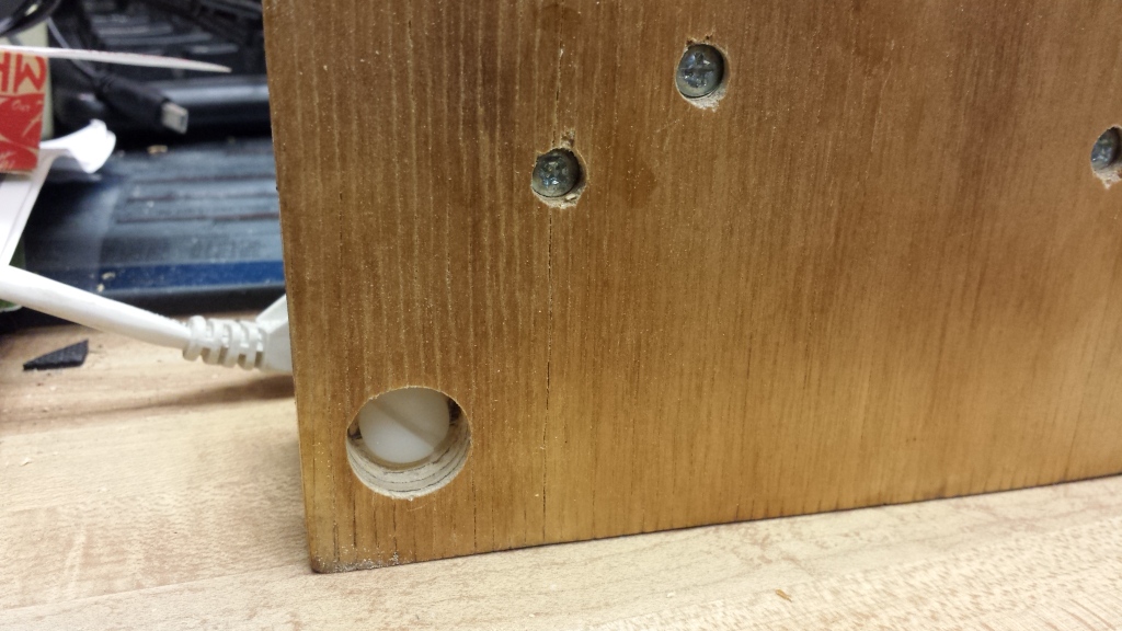
Nylon bolt countersunk
There were a few places where I deviated from the book directions. If I felt it would make it better, without altering the feel of the original, I did it. For instance, I came to the point where I wanted to mount the coil form to the base. In the book, he just called for some longer screws and clamped the coil down tight to the base. I had a problem with that. Two actually. First, wood is a so-so medium for a coil form. Not the worst, but far from the best. Bad enough to have it in the center of the coil but to sandwich it against the side as well was unnecessary. So I wanted to put a spacer between the coil and the base. Also, the idea of sticking two ferrous screws in the form, right at the ends went against everything I knew too. I decided to use plastic – nylon screws/bolts. Off to the hardware store I went. First store, no luck. Second store had 1/4-20 screws up to 1 1/2 inch. I wanted 2 inches, but this was the best I was going to find. Once again, I wanted to recess the heads into the base so it can sit flat, but this was going to be close. I needed about 1/2 inch of countersinking to make the bolts long enough to both go through the coil form and to have one nut between the form and the base as a spacer. It worked, but there is no bolt to spare.
The shims for the variable capacitors are not in the book, either. Apparently, the capacitors the Crystal Set Society sells have the insulators for the stator sticking down slightly and tightening them down against a surface can break them. I might have gotten away with it on a wood surface, but since they had them, I ordered them and used them.
Other than that, it’s pretty much authentic. I made the connections between the coil and the base and it was time to try it out.
I unhooked my 80 meter dipole and put a cliplead to the center conductor. I added another cliplead to the ground in my radio shack and hooked it to the crystal set. I expected to hear our local radio station, which is very strong, and did immediately. I began fiddling with the tuning and it was very broad, with a strong peak at about 2/3rds of the capacitors rotation. Could I hear any other stations? I started hooking in the second capacitor in various configurations. I thought if I could trap out the local station, I might hear others. Using a parallel tuning and parts of the tapped sections of the coil didn’t produce any good null of the local. But I did hear another station in the background. I tried a series configuration and different taps on the coil and got better results. I was able to tune at least two other stations in without hearing the local station at the same time. This is at least as good as, if not better than the results I remember with the original set.
So there it is, my childhood-revisited crystal set. While looking at other sets online, I’ve seen some interesting “DX Sets” that I might emulate and give a try. I’d like to try some Honeycomb or Spiderweb coils made out of Litz wire for more efficiency and higher Q. So many projects!
PDF of the original chapter from The Boys Second Book of Radio and Electronics by Alfred P. Morgan is here