Today I finally got around to working on the 7 Band Portable Dipole I wrote about earlier. I had finished building it, but hadn’t tried it out or even seen if it works.
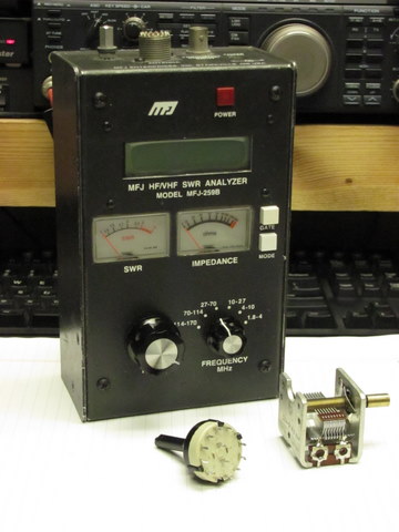
One thing that delayed me was my MFJ-259B antenna analyzer was in pieces. A couple years ago, I dropped it on the floor. It landed face-down and smashed the tuning knob. In the process, it bent the shaft of the tuning capacitor and made it stick and short out as it turned. I ordered a replacement from MFJ and installed it, but it still had problems. It acted flakey. It turned out, although it looked fine upon inspection, the range switch was also damaged and was working intermittently. It sat on the shelf for a couple of years while I decided what to do with it. The antenna project made up my mind to look at it again.
I was dreading tearing into a multi-position rotary switch. I had visions of parts and wires hanging off every terminal. Fortunately, it was a PC-mount switch and every connection went through the PC board. If I could only get it off the PC board without destroying anything, I could replace it. So I carefully disassembled the ‘259 far enough to access the back of the switch. With some care to carefully desolder each pin and a little wiggling, the switch came out. I ordered one from MFJ, along with some of the plastic parts to the push buttons that had also flown off and been lost in the fall.
The new switch and parts came in and were installed. There was no better way to see if it was working than to use it on an antenna. Time to get back to the portable dipole.
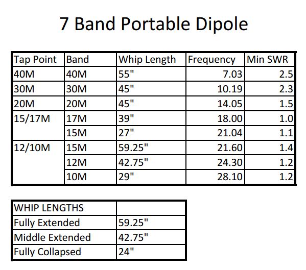
The first thing I did was to go through each tap point and see where it tuned with three settings of the whips: fully extended, fully collapsed, and a middle position with the inner section extended, but the tip section all the way in. I measured from the ball on the tip of the whip to the washer on the bolt at the coil. This gave me three lengths that I can set without a ruler of 59.25, 42.75 and 24 inches.
The first thing I found was 10,12,15,17 and 20 meters all fell within ranges I could reach with the whips at some point. 30 and 40 meters had problems, though.
I found the SWR was a bit higher than I liked on the best 30M setting. I couldn’t make any length work for 40M. I found the 40M tap gave me ranges from 4.7 to 5.0 MHz. so the coil was way too long. I also found another set of resonances on the 30M tap in the same area – 4.7 to 5.1 MHz.
The 10M setting worked but only with the whip fully collapsed. I thought about removing one turn from the ten meter end of the coil. It would be a problem because the connection was sealed inside the end cap and glued. I decided to work on the 40M problem first.
It seemed like with the jumper on the 30M tap, it still wanted to resonate near 4.8 MHz, the same as if it was off. I theorized, that the shorting out of a large number of turns of the coil wasn’t completely removing them from the circuit. Maybe this was why the SWR was higher than I liked on 30M even though it seemed to resonate there.
I decided to disconnect the connection from the boom end of the coils, remove some turns and install a tap point for 40M like the others.
That fixed 30M. I could get a 2.1 SWR with 47″ on the whips at 10.1 MHZ. Not perfect, but close enough.
40M was still way low. I had removed 3 turns on each coil. I decided to try removing 6 turns, but before making it permanent, I decided to solder a short across the last 6 turns to see what happened. It worked and I found I could get a 2.5 SWR at 7.0 Mhz with the whips nearly fully extended at 55″.
So, I made the changes permanent. I moved the new 40M taps down 6 turns and soldered the wire to them. About a foot or more wire was cut off and discarded. Every band can now be set up to work acceptably. The only thing I saw was a slightly high SWR on 30 and 40 meters, but I chalk that up to being so drastically shortened by use of a coil.
I also found that I had placed the 10M tap point on one coil one turn too far in. I hated to do it, but I cut into the wire and removed a turn, then spliced it back together and soldered it. That’s the end that I don’t have access to inside.
These are the optimum lengths I ended up with after all the changes to the coils. I’m pretty happy with them as they all have plenty of room to lengthen or shorten the whips if tuning is needed. I like that 40M uses almost all of the whip length and 30 and 30 meters use quite a bit as well. This should keep efficiency up. The lengths are quite repeatable and I’m confident that I can set them by length and use the tuner to fine tune things.
I noticed that I could also tune 15M with the 10/12 tap and the whips all the way out. It won’t go all the way to the bottom of the band there, though.
Of course, I had to try it out. I put the tools away and brought out the K2 and set it up. I heard a couple pileups on 10M with lots of stateside stations, but I could just about make out the DX station. Not enough to get the call.
I tried 30M next and heard several strong signals. I called CQ a bit but got no answer. I went to 40M and the band was quite good. W1AW was sending code practice with it’s usual rock-crushing signal, but I heard several other stations equally as loud. There were plenty of signals and I’m happy with it’s reception. Unfortunately, it was getting dark and I had to call it quits.
I set the antenna up in the corner of my deck. The railings supported it and it could stick out into the air on both sides there. The deck is also quite high off the ground there, probably eight feet, so the dipole was at least 12 feet above the ground. I still need to figure out a tripod/pole or other mounting arrangement. I probably won’t be using this too much over the winter months, so I’ve got until Spring to work on that!
I also didn’t find time for photos. I’ll work on that later and add them to this post.


